F5 SSL Orchestrator allows companies to secure their enterprises and provides the scale necessary to prevent various attack types, vectors, and presentations while offering uncompromising visibility into data traffic traversing diverse security zones. When combined with a strong distributed denial-of-service (DDoS) strategy, SSL Orchestrator and its integration with Cisco Firepower Threat Defense (FTD) deliver the necessary components of perimeter security and provide comprehensive protection by protecting the enterprise from malware, bots, and other attacks.
To achieve seamless integration, F5 partnered with Cisco to validate and produce reference architectures for integrating SSL Orchestrator and Firepower Threat Defense. Testing and validation were conducted at the F5 Labs facilities using both virtual and physical Firepower devices with FTD.
This guide helps administrators identify and deploy validated configurations for common use cases. The customer scenarios defined here address policy-based traffic steering and blocking as well as SSL visibility and control.
This scenario employs SSL Orchestrator to allocate traffic flows to different resources based on load. Alternately, is allocates using business intelligence, based on features such as centralized policy management or F5 iRules for deeper decision-making processes, which FTD resources can leverage for inspection. For example, Application A can be directed to one pool of FTD servers with a specialized ruleset that monitors signatures specific to its environment, while Application B is directed to another pool. Integration with the Firepower remediation API allows the system to dynamically react to reduce the demand on FTD infrastructure by using an iRule to populate an IP address into a block list. Traffic from the identified offender is blocked before entering FTD for a preset period of time. Since one strategy of attackers is to provide an overwhelming amount of distracting traffic to mask the real attack, this remediation tactic can allow FTD to focus resources on identifying new attacks without having to remediate already identified attackers.
SSL termination is a resource-intensive process, but F5 devices include dedicated hardware processors specializing in SSL processing. For both inbound and outbound deployment scenarios, utilizing SSL Orchestrator plus FTD provides uncompromising visibility into SSL traffic.
Inbound applications are rarely deployed without high availability in mind, and SSL termination on an F5 BIG-IP instance ensures secure and enhanced application delivery while providing FTD sensors with visibility into SSL traffic. Where security policy dictates, traffic can be re-encrypted before being passed to the back-end servers.
The proliferation of websites now using SSL encryption to protect users poses a challenge to FTD sensor pools in their mission to eliminate malware and attacks. SSL Orchestrator can provide full visibility into user traffic.
SSL Orchestrator supports inbound SSL/TLS inspection to prevent encrypted threats from going undetected and compromising critical assets. Protects your apps and servers by eliminating security blind spots and stopping hidden threats.
The validated architecture contains a load-balanced pool of Firepower devices front-ending web application server pools. This approach maximizes the effectiveness of the combined Cisco and F5 solution while it addresses both SSL visibility and control and traffic management and blocking. The inspection zone traffic is decrypted long enough to be inspected by the Firepower devices and re-encrypted before being sent to the application server or client.
In Figure 1, the Firepower Services inspect, block, and report on all network flows. After traffic traverses the FTD devices, it is then routed back through SSL Orchestrator. This ensures that traffic can be inspected, and, if necessary, IP addresses can be blocked.

SSL Orchestrator supports outbound SSL/TLS inspection to stop malware from penetrating the corporate network and to prevent command and control (C&C) communication through encrypted channels. The solution halts malware infections, data exfiltration, and C&C communications.
The validated architecture protects internal clients from Internet-based threats. Clients access the Internet through SSL Orchestrator, which decrypts this traffic and sends a copy of it to the Firepower devices for inspection.

These procedures assume the existence of a working SSL Orchestrator topology, either incoming or outgoing, and focus on adding a Cisco Firepower TAP Service, including these steps:
Both topology types are supported, and configuration of the Cisco remediation solution is the same. If you do not already have a working SSL Orchestrator topology, refer to the SSL Orchestrator article series on F5 DevCentral for full configuration steps.
This guide outlines the necessary steps to deploy Cisco FTD with SSL Orchestrator, including configuration of the Firepower Services (Firepower nodes), security policy, and the application of iRules. FTD can be deployed as a layer 2/3 or TAP solution. SSL Orchestrator can be deployed as a layer 2 or 3 solution. SSL Orchestrator provides the flexibility to deploy in the manner that works best for you. For example, SSL Orchestrator can be deployed in layer 2 mode while FTD is deployed in layer 3 mode, and vice versa.
A familiarity with F5 deployment concepts and technology as well as basic networking is essential for configuring and deploying SSL Orchestrator. For further details on configuration and networking setup, please visit the F5 support site, AskF5.
Although the Guided Configuration wizard will help configure most of this solution, a few things must be done outside of it. This example uses an existing L2 outbound topology.
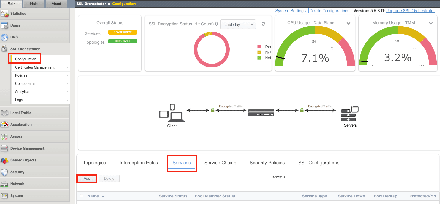
1. In the Configuration Utility, click SSL Orchestrator > Configuration > Services > Add.
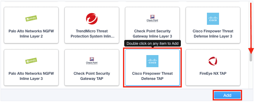
2. Under Service properties, select Cisco Firepower Threat Defense TAP and click Add.
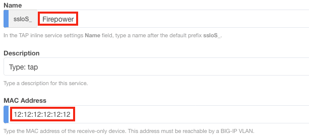
3. Name the service and enter the Firepower MAC Address (or 12:12:12:12:12:12 if it is directly connected to SSL Orchestrator).
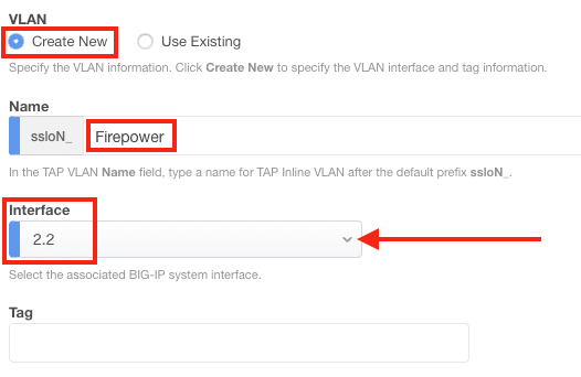
4. Under VLAN, click Create New, enter a Name (e.g., Firepower), and select the correct interface (2.2 in this example). Or if you previously configured the VLAN, click Use Existing, then select the appropriate VLAN from the drop-down menu.
Note: Specify a VLAN tag if needed.
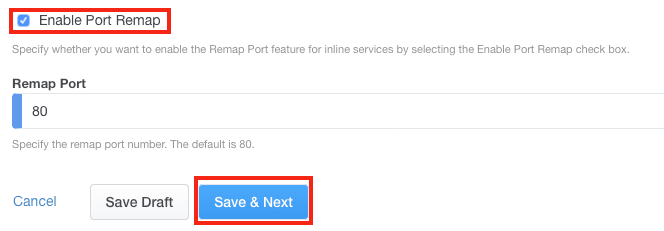
5. Enabling the Port Remap is optional. Click Save & Next.
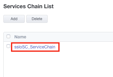
6. Click the Service Chain you wish to configure (sslo_SC_ServiceChain in this example). If you don’t have an existing service chain, add one now.
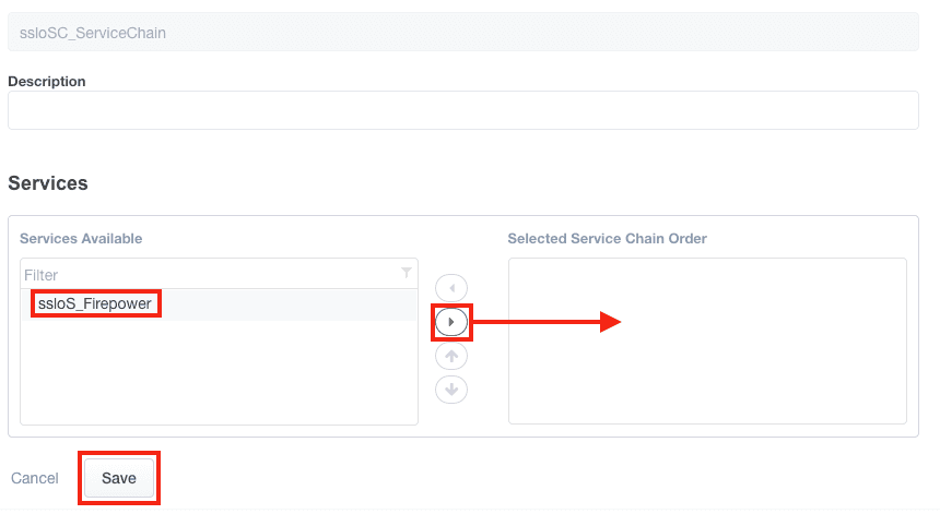
7. Select the Firepower service and move it to the Selected list by clicking the appropriate arrow. Click Save.
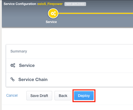
8. Click Save & Next and then click Deploy.
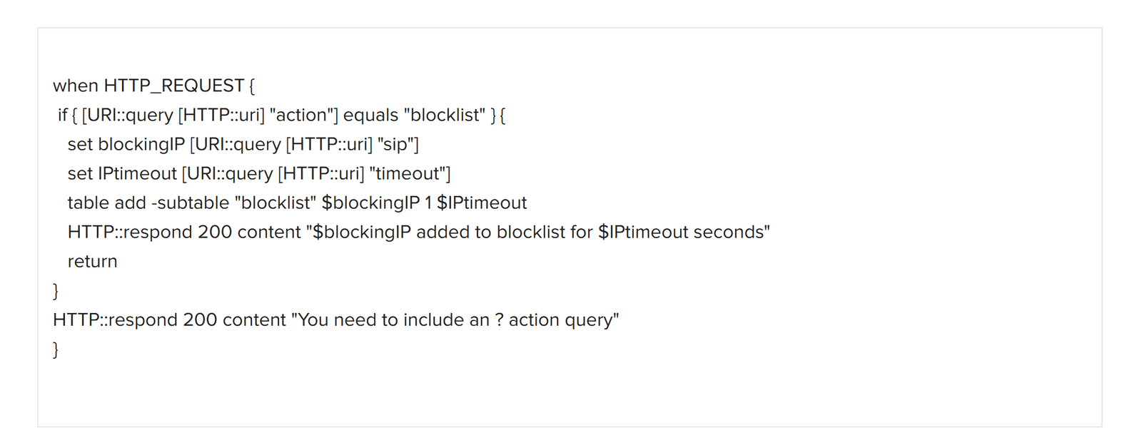
Create two iRules and two virtual servers. The first iRule listens for HTTP requests from the Firepower device. Firepower then responds via its Remediation API and sends an HTTP request containing an IP address and a timeout value. The address is the source IP to be blocked by SSL Orchestrator, which will block it for the duration of the timeout period. For details and iRules tutorials, please consult F5 DevCentral.
1. Create the first iRule on SSL Orchestrator by selecting Local Traffic > iRules and then clicking Create.
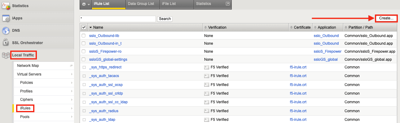
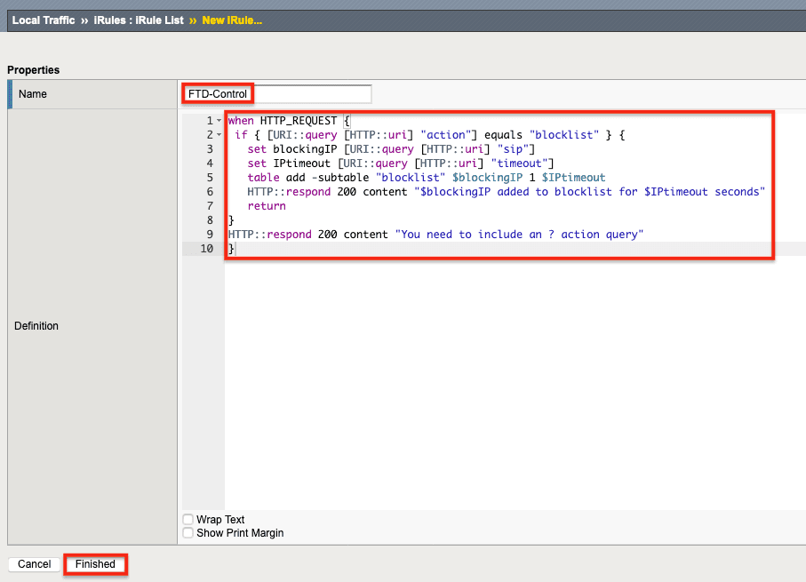
2. Name the iRule (FTD-Control in this example) and then copy and paste the text of the iRule (in Figure 3 below) into the Definition field. Click Finished. This iRule will be associated with the Control virtual server.
3. Create a second iRule by clicking Create again.
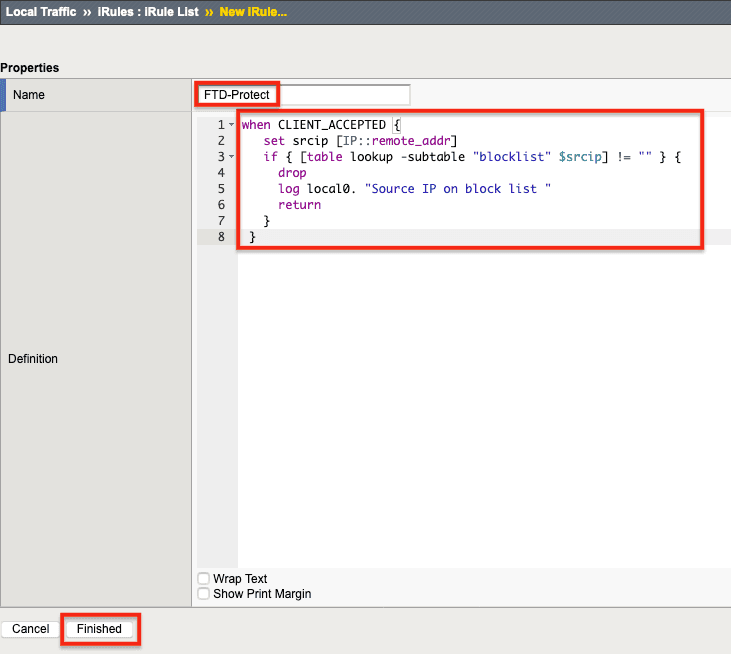
4. Name the second iRule (FTD-Protect in this example) and then copy/paste the iRule text in Figure 4, below, into the Definition field.
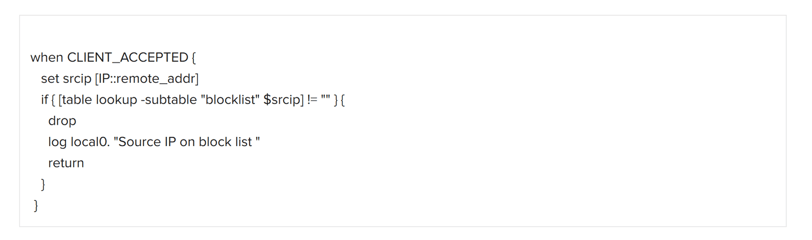
5. Click Finished. This iRule will be associated with the Protect Virtual Server.
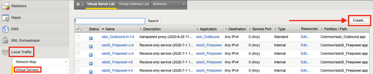
1. Create the virtual servers by selecting Local Traffic > Virtual Servers and clicking Create.
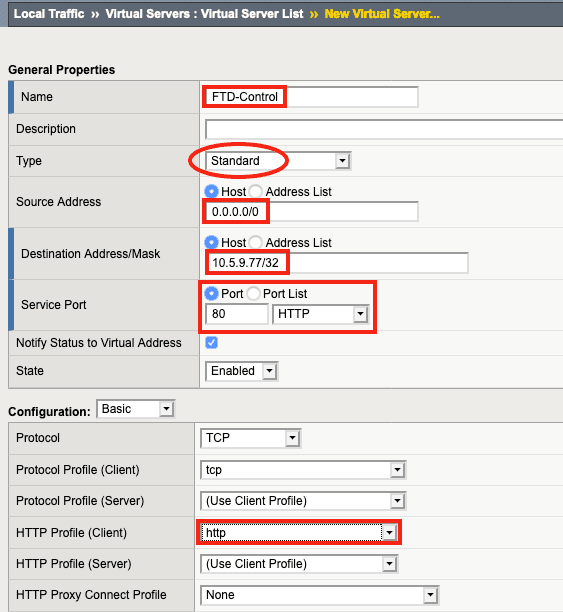
2. Name the virtual server (keeping in mind the name of the associated iRule)—FTD-Control in this example. For Type, select Standard.
3. For Source Address, enter 0.0.0.0/0, which indicates that any source address will match.
4. For Destination Address/Mask, enter the IP address SSL Orchestrator will listen on to accept API requests from Firepower. (In this example, it’s 10.5.9.77/32, which indicates that SSL Orchestrator will only respond to connections to that single IP address.
Note: The destination address/mask must be in the same subnet as the Second Management Interface on the Firepower Management Center, which will be discussed later in this guide.
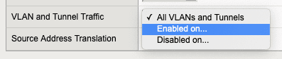
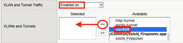
5. For VLANS and Tunnel Traffic, F5 recommends selecting Enabled on… the specific VLAN that the Firepower Second Management Interface will be using, rather than All VLANs and Tunnels.
6. Select the same VLAN that will be used by the Firepower Second Management Interface (vlan509 in this example). Click the << to move the correct VLAN to the Selected list.
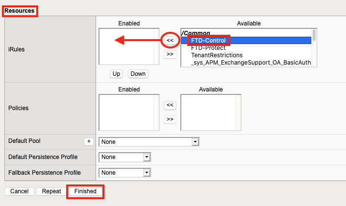
7. Under Resources, click the FTD-Control iRule created previously and click << to move it to the Enabled list, then click Finished.
8. To create the second virtual server, click Create again.
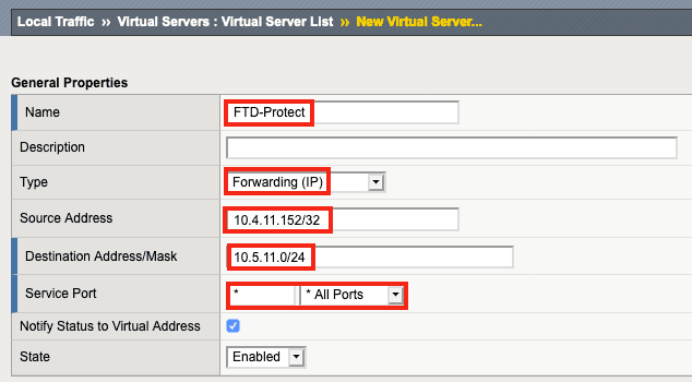
9. Name the virtual server (FTD-Protect in this example) and for Type, click Forwarding (IP).
10. Enter the Source Address (10.4.11.152/32 in this example). This virtual server will only accept connections with a source IP of 10.4.11.152 for testing purposes, to make sure everything works with a single test client. For an inbound topology, the Source Address might be set to 0.0.0.0/0, which would allow connections from anywhere.
11. Enter the Destination Address/Mask. In this case, the 10.5.11.0 network is the destination 10.4.11.0 network traffic must take to pass through SSL Orchestrator and proceed to the Internet.
12. Under Configuration, select Enabled on… for VLAN and Tunnel Traffic.
13. Under Available, select the ingress VLAN that SSL Orchestrator is receiving traffic on (Direct_all_vlan_511_2 in this example). Click << to move it to the Selected list.

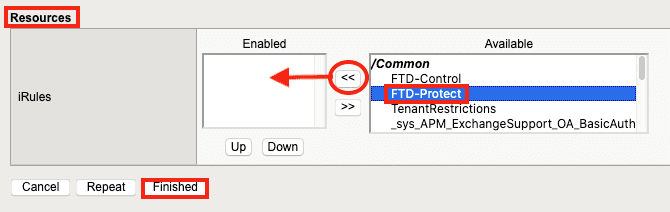
14. Under Resources, click the FTD-Protect iRule created previously. Click << to move it to the Enabled list, then click Finished.
You have now:
These procedures assume Cisco Firepower and Firepower Management Center (FMC) have been licensed and deployed and are working properly.
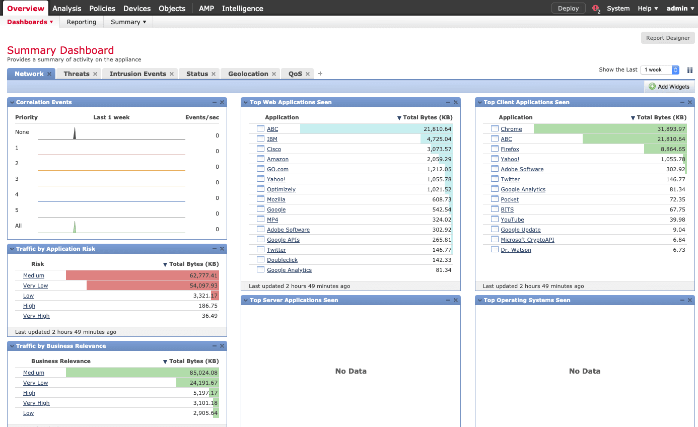
1. Log in to the Firepower Management Center to view the Summary Dashboard.
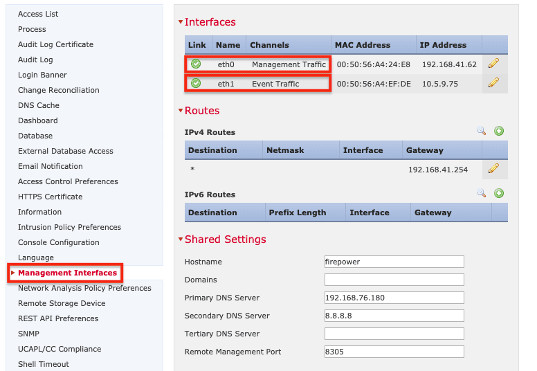
2. Click System > Configuration. (The Devices tab will open.)

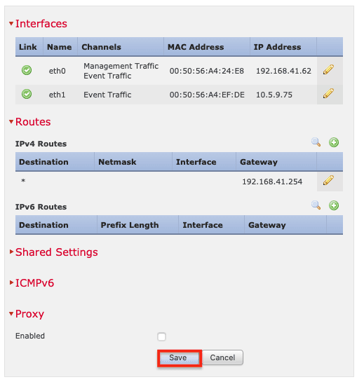
3. Click Management Interfaces in the menu on the left. An FMC management interface must be configured for event traffic and must be on the same subnet as the Control Virtual Server on SSL Orchestrator (10.5.9.77 in the examples).
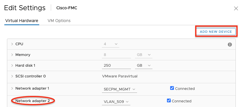
4. When using a virtual machine for FMC, click Add New Device and add a second NIC within the Hypervisor console. (Refer to the screenshot below and your Hypervisor admin guide for more information on how to do this.)
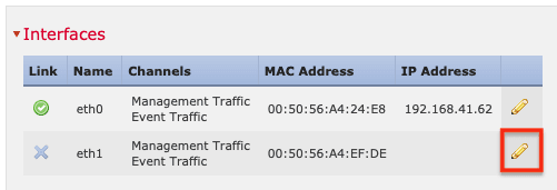
5. To configure the second management interface, click the pencil (edit) icon.
6. Select Enabled. (Event Traffic must be enabled but Management Traffic is not required.)
7. Set IPv4 Configuration to Static. Enter the IP address and subnet mask, then click OK.
Note: This interface must be on the same VLAN and subnet as the control interface on SSL Orchestrator.
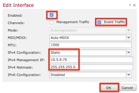
8. Click Save.
This guide assumes that intrusion and malware policies, which should look something like the example below, are enabled for the Firepower device.
Next, create a Firepower remediation policy. A remediation policy can take a variety of actions based on an almost infinite set of criteria. For example, if an intrusion event is detected, Firepower can tell SSL Orchestrator to block the source IP for a certain amount of time.
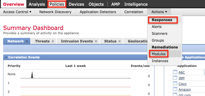
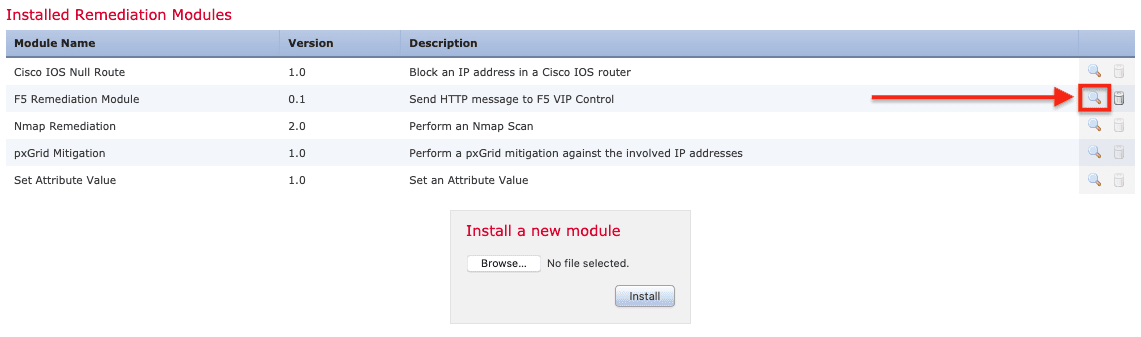
1. Install the F5 Remediation Module. To do so, in the FMC, click Policies > Actions > Responses > Modules.
2. Click Browse to locate the F5 Remediation Module on your computer. Select it, click Open, and then click Install. Once it’s installed, click the magnifying glass on the right.
3. Click Add to configure an instance.
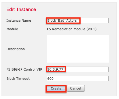
4. Name the instance (Block_Bad_Actors in this example). Enter the IP address of the SSL Orchestrator Control Virtual Server (10.5.9.77 in this example). Changing the Timeout is optional. Finally, click Create.
5. Next, under Configured Remediations, click Add.
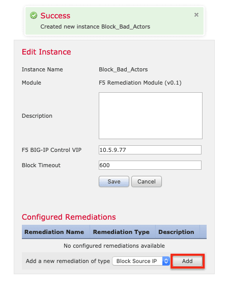
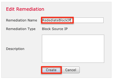
6. Name the remediation (RemediateBlockIP in this example), and click Create.
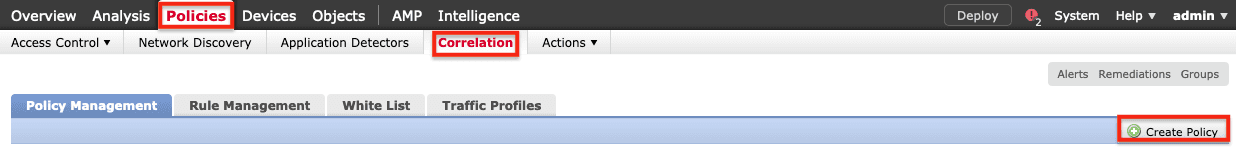
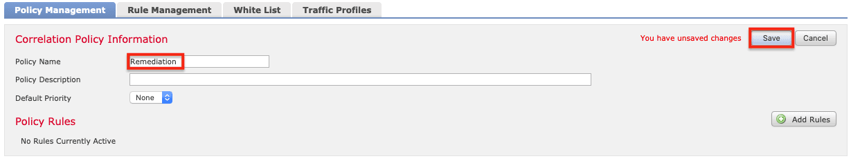
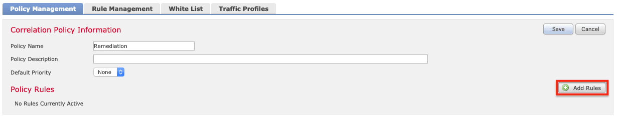
7. Select Policies > Correlation > Create Policy to create a Correlation Policy, which will define when and how to initiate the remediation.
8. Name the correlation policy (Remediation in this example) and click Save.
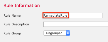
9. On the Rule Management tab, click Create Rule.

10. Name the rule (RemediateRule in this example).
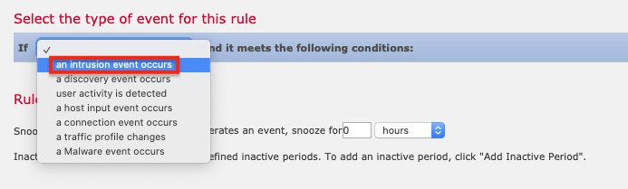
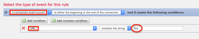
11. For the type of event, select an intrusion event occurs. (For testing, also see the note in the next step.)
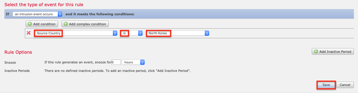
12. For the Condition, select Source Country > is > North Korea (for example), and then click Save.
Note: The FMC can trigger a remediation for a variety of different events, not only intrusion. In fact, while configuring remediation you might want to use a different event type to make it easier to trigger an event and verify it was successfully remediated. For example, choose a connection event occurs then set the Condition to URL > contains the string > foo. Then the remediation rule should trigger if you attempt to go to foo.com.
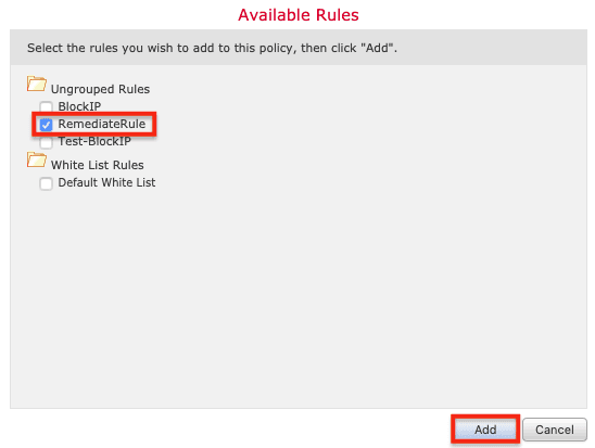
13. Return to the Policy Management tab and click the policy created previously (Remediation in this example). Click Add Rules.
14. Select the RemediateRule and click Add.
15. Click Save.
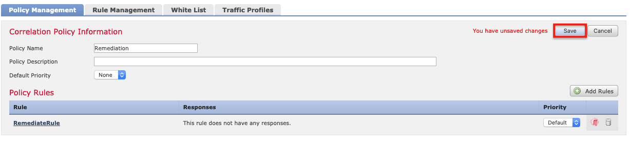
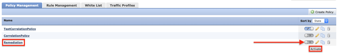
Correlation policies can be enabled or disabled using the toggle on the right. Make sure the correct policy is enabled.
The status of remediation events can be viewed in the FMC by clicking Analysis > Correlation > Status. See the Result Message column for the “Successful completion of remediation” message.
These recommended practices configure F5 BIG-IP SSL Orchestrator with the Cisco FTD in an architecture demonstrated to address both the SSL visibility and control user scenario and the IPS policy-based traffic steering and blocking user scenario. With SSL termination on SSL Orchestrator, FTD sensors provide visibility into both ingress and egress traffic to adapt and protect an organization’s applications, servers, and other resources. Using security policy-based traffic steering, an organization can capitalize on this configuration and continue to scale, adding more FTD-managed devices to provide greater traffic capacity for the protected networks and applications. The policy-based flexibility provided by SSL Orchestrator can also be leveraged to selectively direct traffic to different pools of resources based on business, security, or compliance requirements.
PUBLISHED OCTOBER 09, 2020