
Building an Enterprise Cloud with F5 and IBM
Introduction
By some estimates, the enterprise cloud—also known as the private cloud—is being adopted at a faster pace than the public cloud. Enterprise consulting firm Accenture places private cloud enterprise penetration at 77 percent by the end of 2011.1 Much of this rapid move to create an agile on-site infrastructure stems from the need, on the part of large and small enterprise IT departments, to maintain in-house control and management of both the infrastructure and the data.
Once the decision is made to adopt a cloud infrastructure, the choice between internal/private and external/public comes down to an analysis of cost, risk, and value. A public cloud typically offers a flexible approach and the most cost savings; however, it carries risks associated with security, service-level agreements (SLAs) and availability, and management. IT can take advantage of near limitless scale at a low cost of entry, but it sacrifices control. Moving from a traditional on-site or hosted data center to an external public cloud is basically like moving your entire data center into someone else’s hands.
With an enterprise cloud, IT has the level of control it requires and avoids the risks associated with a public cloud; but a private cloud is more expensive to deploy, requires additional levels of knowledge and expertise by the staff, and adds a higher level of complexity to the on-premise data center. The enterprise cloud infrastructure can be scaled as necessary and provides dynamic provisioning and agility, but that scale and control often comes with a higher cost of entry.
Together, F5 Networks® and IBM have designed a reference architecture for the enterprise cloud that alleviates many of the challenges associated with complexity. It brings many of the architecture and scale components of a public cloud on-premise to significantly reduce the cost of building an internal, piecemeal system. By predefining required components and outlining how those components work together, F5 and IBM have created a complete, dynamic, and agile enterprise-cloud infrastructure.
Workflow
The most important element of an on-demand provisioning system is the ability to make decisions and take action based on events. An event somewhere in the system creates an alert or message that is picked up by a component (either one that has subscribed to the message bus or one that has been directly requested via an API call), which then acts on that message. Wor kflow is the process and order in which components act on system messages.
In an enterprise cloud, the workflow typically breaks down into provisioning components that either request or relinquish resources, and the steps required to manage resource allocation. As a virtual machine (VM) needs additional CPU resources, a workflow is initiated to determine where those CPU resources will come from, start a new VM, allocate an IP address, and so forth.
Workflow Architecture
The F5 and IBM enterprise cloud architecture is based on two critical tenets:
- There is a centralized message bus used to carry event notification messages, and all components that have to act on events are tied to the bus.
Beyond these two principles, the F5 and IBM reference architecture is extremely malleable, which means it can fit into any existing data center or cloud architecture. If an orchestration engine already exists to manage VM deployment, for example, this reference architecture can be adapted so the existing engine can be used. One misconception in regard to building an enterprise cloud is that the entire infrastructure has to be replaced; the F5 and IBM solution was created to integrate with existing components at every possible step.
Workflow Components
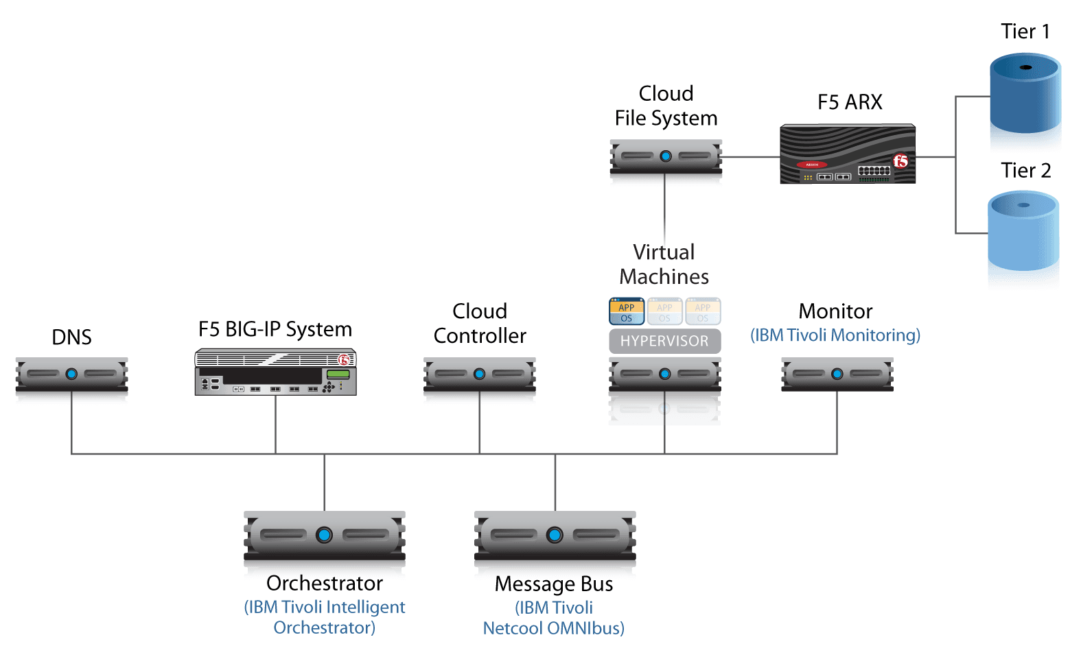
Regardless of which components already exist and which ones are new, the enterprise cloud workflow is composed of specific components that perform specific tasks. The entire cloud system is composed of these individual components, which work together to provide the complete cloud infrastructure. That infrastructure is powered and controlled through component workflows — coordinated tasks that manage a cloud event.
Message Bus
The message bus is the system that carries messages based on events and alerts to each component that is affected. As an event triggers a message, that message is sent across the message bus to a particular component, which has rules on what to do with that message. The message bus is also responsible for normalizing messages based on rules for specific components.
The F5 and IBM reference cloud architecture uses the IBM Tivoli Netcool OMNIbus solution as the central message bus, however any enterprise message bus can be used to carry event notifications throughout the system.
Orchestrator
The orchestrator can be thought of as the brains of the enterprise cloud—the component responsible for making most of the macro provisioning decisions based on messages received over the bus. The orchestrator will kick off major events and workflows in the cloud architecture, such as starting the “provision new virtual machine” workflow. The orchestrator is also responsible for fetching data required for each workflow and providing it to the applicable components; for example, the orchestrator would provide IP address information needed to provision a new VM.
For the reference architecture, the orchestrator is created by using a series of interpreted scripts that act on messages from the bus and start workflow events. Any type of orchestrator, such as IBM Tivoli Intelligent Orchestrator, HP Operations Orchestration, or VMware vCenter Orchestrator, can be used.
Cloud Controller
The cloud controller is the front-end system responsible for gathering and aggregating the preliminary data required to start a provisioning process. Initially, this information is provided by an administrator as part of the creation process and is specific to each type of workflow used for provisioning. For example, the cloud controller gathers information that includes VM location, class of application (web server, database server, mail server, etc.), and minimum resource requirements.
During an automated provisioning event, and once this preliminary data has already been stored in the system, the orchestrator requests and extracts the existing information to seed the provisioning workflow. Examples of cloud controllers include Eucalyptus Cloud Controller, VMware vCloud Director, or Amazon EC2. For future growth and expandability into other cloud platforms, it is good practice to choose a cloud controller that can either integrate or communicate with a standard set of cloud APIs. This enables the cloud controller to extend into a public or hybrid cloud provider without re-architecting the enterprise cloud platform.
Cluster Controller/Hypervisor
The cluster controller is the component in the enterprise cloud responsible for managing the virtual machine that is being provisioned, as well as the storage and metadata required to run the VM. As the VM running environment, the cluster controller includes the virtual platform hypervisor and can also include the larger hypervisor management environment. For example, the cluster controller might be a bare-bones hypervisor, such as VMware ESXi, or a larger collection of distributed hypervisor systems, such as VMware vSphere or VMware vCloud.
Monitoring
Health and status monitoring are essential elements of any enterprise application deployment. Monitoring also provides status updates for provisioning systems, for example, when a virtual machine is up and answering connections on the network. Continuous monitoring of the system can provide real-time alerts that ultimately feed into new workflows and affect provisioning decisions. Any component that is capable of monitoring application and network status can be used in the enterprise cloud deployment; however, IBM Tivoli Monitoring software is used in the F5 and IBM reference architecture.
DNS
Domain Name System (DNS) plays a critical role in the F5 and IBM enterprise cloud reference architecture: It is responsible for storing not only the IP and domain name information for IPv4 and IPv6, but also system metadata, such as the information gathered by the cloud controller and unique machine identification information. For this reference architecture, DNS was chosen as the storage location for metadata because it is a standards-based system that already exists in most networks, it is available to all cloud components, and it alleviates the requirement of adding additional database-type storage to the infrastructure. Any DNS solution that is managed by IT and has the ability to add additional zones and zone files can be used.
Storage
For the F5 and IBM reference architecture, the cluster controller runs the virtual machine from local storage; however, when it is not running, the VM virtual disk is on virtualized storage. During a workflow provisioning event, the cluster controller will request the virtual disk from the virtual storage device over Network File System (NFS).
Application Delivery Controller
The last component in the enterprise cloud is the Application Delivery Controller (also referred to as the load balancer), which, in the F5 and IBM reference architecture, is F5® BIG-IP® Local Traffic Manager™ (LTM). BIG-IP LTM manages connections, services, and delivery of the application data coming from the virtual machine. Ultimately, BIG-IP LTM is the final part of the system that acts on a workflow provisioning event.
Walk-Throughs: Manual and Automated Provisioning
The goal of the F5 and IBM enterprise cloud reference architecture is to provide a real-world, resource-based platform for dynamically deploying applications. Once all the components are in place, they work together—through various workflows—to provision new application services as needed. There are two ways to provision systems that are in place in the enterprise cloud: manual provisioning and automated provisioning.
Manual Provisioning
Typically, the first workflow in the enterprise cloud is initiated from a manual process based on input from the system administrator or application requestor. That’s not to say that workflow is manual; only the act of inputting information into the system for the first time is manual. Once data is gathered from the administrator, the system begins predefined automated workflow events for application provisioning.
Step 1: Cloud Controller Data Entry
Using the cloud controller GUI, the administrator (or application requestor, depending on who is responsible for starting a new provisioning event) enters the information required to spin up a new virtual machine and bring an application online. This information is usually higher-level infrastructure data, such as:
- Application type: A predefined list of available application types, such as Microsoft SharePoint, a web server, a mail server, an Oracle database, etc.
- Network information: Cluster IP address, front-end URL, whether this application will be public-facing or internal-only, etc.
- Provisioning information: Any additional information required for the provisioning system, such as network location (often a geographic reference tied to a physical data center, for example, “Europe– Copenhagen Data Center”), and any restrictions on the minimum and maximum number of allowed instances of a given application type.
This information is used as metadata for automated provisioning throughout the enterprise cloud.
Step 2: Initiate Provisioning Workflow; Distribute Metadata
Once the administrator submits the required data, the next step is for the cloud controller to package that information—along with a dynamically created unique instance ID used throughout the system to identify this instance for provisioning, such as “vm12345”—and distribute it to the orchestrator over the message bus.
All information provided during the first step is normalized by the message bus before delivery to the orchestrator.
In tandem, the cloud controller provides the same metadata and unique instance ID to the hypervisor, via an API, and instructs it to deploy the required application image. This event prompts the hypervisor to request the applicable virtual machine disk image from cloud-based storage. The storage device retrieves the appropriate disk image over NFS and begins copying that image to local storage.
Step 3: Orchestrator Distributes Metadata
After the orchestrator has received the normalized event information and metadata from the message bus, it then kicks off two different workflows that simultaneously push the metadata to the monitoring system(s) and DNS. The monitoring system(s) use this information to configure an automated monitoring schedule for the application and begin monitoring the application after notification that is up and running. During this step, the orchestrator will also define thresholds for the monitoring system events — for example, instructing the monitor to send an event notification when the CPU of this virtual instance exceeds 75 percent utilization.
The orchestrator also pushes the virtual instance metadata to DNS, where that data is stored for use throughout the entire enterprise cloud. The orchestrator is responsible for submitting the metadata in the appropriate DNS zone format, so it must construct domain names based on the instance ID, create IPv4 and IPv6 DNS records, add instance information from the cloud controller, and add the new instance information to the appropriate zone. For example, the orchestrator will take the unique instance ID, create a DNS entry for “vm12345.vm.cloud.example.com” and add that to the existing example.com zone.
The final step in distributing metadata throughout the enterprise cloud is to populate the BIG-IP LTM Application Delivery Controller with the new instance information, such as hostname, IP address, application type (or pool on BIG-IP LTM), and monitoring information.
Step 4: Virtual Machine Notification
In step 2, the cloud controller instructed the hypervisor to start the virtual machine associated with the newly provisioned instance. Once that VM is up and running as expected and available for connections, it will notify the orchestrator via an event alert on the message bus. The orchestrator will take that event alert and start a workflow that instructs BIG-IP LTM to flag the new VM as available in the pool, and to begin sending and distributing new connections to the virtual instance based on the load balancing method. BIG-IP LTM will also begin monitoring the new instance with the previously configured application monitor assigned to the application pool.
The event alert from the newly running VM will also prompt the orchestrator to notify the overall enterprise cloud monitoring system to begin monitoring the virtual instance. At this point, the newly provisioned virtual instance is up and running in the enterprise cloud and handling application service requests. This is the normal operating mode of all services that are part of the enterprise cloud.
Automated Provisioning
Manual provisioning is the first workflow step in provisioning services within the enterprise cloud, but it is not the most frequent form of provisioning. In a smooth-running system, the enterprise cloud moves to a more dynamic and fluid system of self-monitoring, and it self-provisions new services as needed and based on demand. This agile self-provisioning is at the heart of any cloud platform, and it requires additional automated provisioning events and workflows for monitoring and reacting to real-time events.
Step 1: Monitoring and Alerts
The first step of any auto-provisioning system is monitoring: gathering and detecting events throughout the system. During the first round of manual provisioning, the monitoring systems were populated with virtual instance information such as name, location, type of monitoring, and event thresholds. This information is used to automatically monitor the availability and performance of the applications and virtual instances. Once an event—for example, a given virtual instance consuming more than 75 percent of available CPU resources — is detected by the monitoring system, it will generate an event on the message bus that alerts the orchestrator to the depleted resources.
Step 2: Data Gathering
In a typical automated provisioning scenario, the orchestrator is responsible for creating a new virtual instance that will help alleviate the resource load on the current instance. Two or more of the virtual instances will be used to distribute the application computing and network loads.
To initiate an automated provisioning workflow, the orchestrator must be responsible for collecting component events, as well as requesting metadata required to provision a new virtual instance. In the F5 and IBM reference architecture, the metadata is stored in DNS and populated as part of the original manual provisioning workflow. DNS will return information—for example, application type, geographic location, and provisioning thresholds—to the orchestrator such as application type, geographic location, and provisioning thresholds.
Step 3: Kicking Off the Workflow
In the final step of an automated provisioning workflow, the orchestrator pushes the metadata acquired from DNS to the cloud controller over the message bus. Essentially, this automated step simulates the step in which an administrator enters machine information and manually starts the provisioning workflow. The cloud controller will take in this information (just as it would from the administrator in manual provisioning) and begin a new virtual instance provisioning workflow. From this point on, the provisioning steps and workflows detailed above are repeated until the new virtual instance is up, running, and accepting new connections.
A typical enterprise cloud deployment will include both manual and automated provisioning workflows. New services or applications will be initially deployed using a manual workflow so that an administrator can control how and where the service is deployed. Once a service is up and running, the automated provisioning workflows will manage provisioning based on resource needs and availability.
Conclusion
Choosing to deploy a private enterprise cloud should not come at a cost of increased complexity or inoperability. The purpose of any cloud deployment is to reduce the barriers of creating new services and provide a more agile computing infrastructure. An enterprise cloud brings that agility into the data center for significantly improved manageability and control.
With IBM, F5 has created a reference architecture for an auto-provisioned enterprise cloud. This architecture is designed to be modular and flexible—enabling existing components to be integrated as needed, and for the entire enterprise cloud to be connected to any other cloud platform via APIs and a shared messaging infrastructure. No private enterprise cloud is quite the same; however, the F5 and IBM architecture will adapt to different environments, while bringing the benefits of an agile infrastructure to any application deployment or data center.
1 Babcock, Charles (2011, January 18). “Private Clouds Taking Off.” Information Week. Web.
PUBLISHED JANUARY 10, 2012